
-
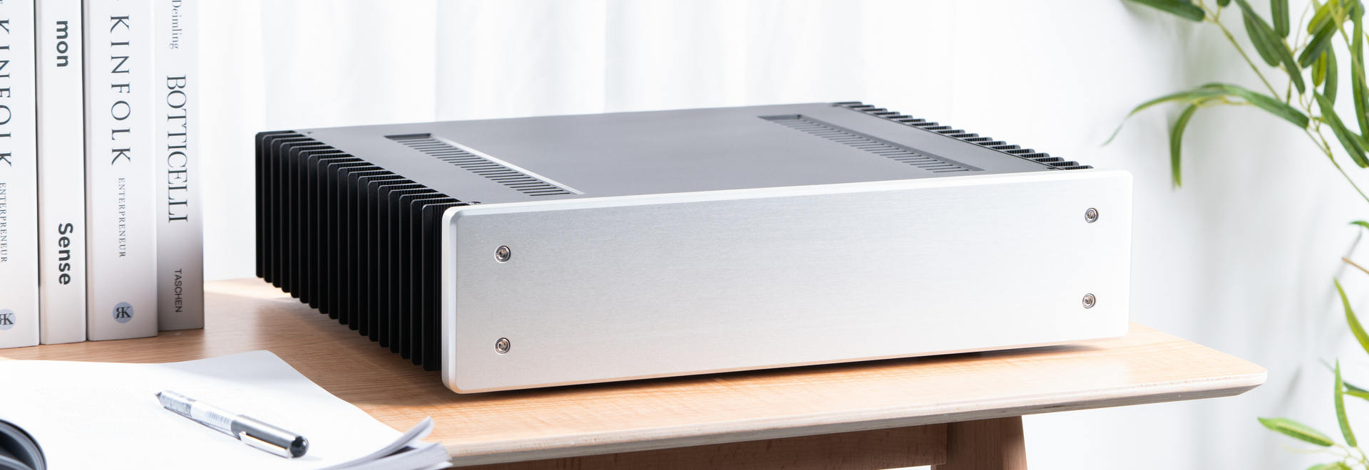
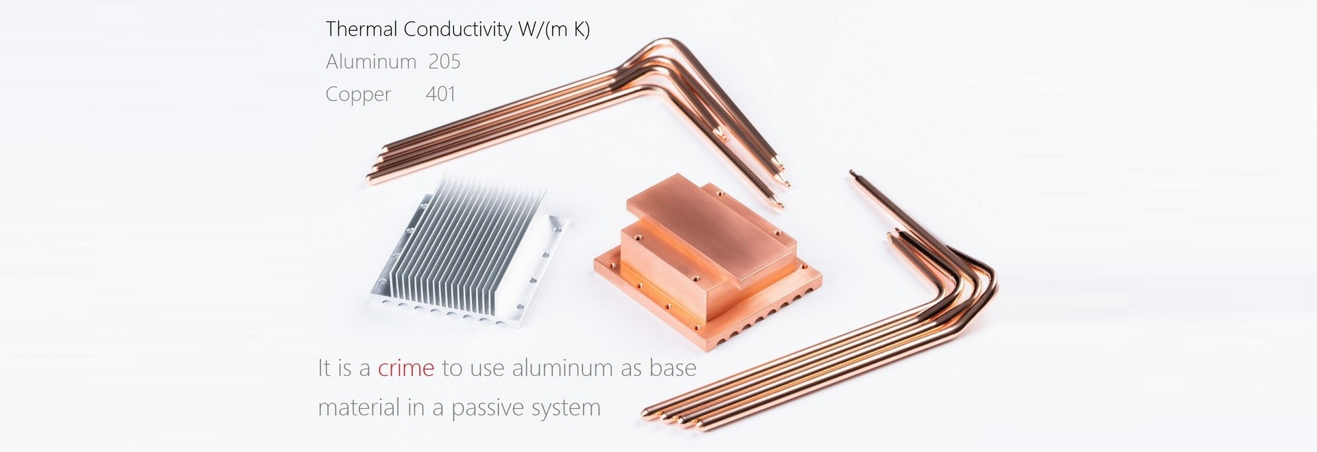
 HDPLEX H5 Fanless ChassisEight-heatpipe copper base CPU heatsink system. A flagship achievement. Support passive cooling 125W TDP CPU and passive GPU heatsink system.
Free Shipping Worldwide -
 HDPLEX H1 V3 Fanless ChassisSmall footprint low profile fanless PC chassis for mini-ITX and Thin-ITX. Full internal HDPLEX 250W GaN AIO ATX PSU solution. H1 V3 also supports 7/8th Gen NUC with the addition of HDPLEX NUC kit.
Free Shipping Worldwide
-
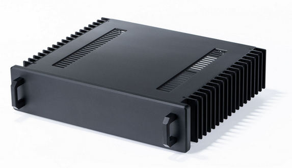
 HDPLEX H3 Fanless PC ChassisSupports ITX/microATX and dual low profile PCIE Expansion card. Supports 85W TDP CPU via eight-heatpipe passive CPU heatsink system. Supports HDPLEX 200W and 400W NanoATX Fully Internal Power Supply Solution.
Free Shipping Worldwide -
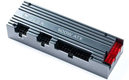 HDPLEX 500W HiFi DC-ATXMarket leader in DC-ATX section. Supports 12V-48V Wide Range Input. True 45A with 55A peak for 12V. Monster-size inductors guarantee no coil whine at peak load.
Free Shipping Worldwide


